

Introduction
AutoCAD has become the standard drafting tool for facilities layout planning across warehouses, distribution centers, and manufacturing facilities. Facility managers, operations engineers, and material handling specialists use it to plan space before a single rack or shelf is installed — catching conflicts on paper rather than discovering them after equipment is bolted down.
According to IFMA and Autodesk, 85% of facility operators struggle with poor-quality data, and operations absorb 68% of costs tied to poor data interoperability. Pre-installation layout drawings exist specifically to prevent that.
Getting a layout right means more than knowing the software. Scale, clearance requirements, equipment footprints, and operational flow all have to be accurate before the drawing is useful to anyone installing equipment.
This guide covers how AutoCAD is applied to warehouse and storage layout planning: when to use it, what the process looks like step by step, and what separates a drawing that guides installation from one that gets ignored.
Key Takeaways
- Use AutoCAD before purchasing or installing racking, shelving, mezzanines, or dock equipment — not after
- Required inputs: building dimensions, ceiling heights, column locations, door/dock positions, and equipment spec sheets with footprint data
- Core process: set up the drawing file, draw the floor boundary, place scaled equipment blocks, then dimension and annotate
- Measured dimensions are non-negotiable — rough estimates are the leading cause of layout errors
- The finished drawing should be legible enough for installers to work from directly
When Should You Use AutoCAD for Facilities Layout?
AutoCAD delivers real value at the planning or reconfiguration stage — before committing to purchasing or installing storage systems. Using it after equipment is installed is damage control, not planning.
Situations Where AutoCAD Is Appropriate
- New facility buildouts: Maximize storage positions and traffic flow before construction is finalized
- Warehouse expansions: Model how new storage systems connect to existing infrastructure
- Storage system upgrades: Switching from floor-stack to pallet racking, adding a mezzanine, or reconfiguring pick paths in an underutilized bay
- Operational flow reorganizations: Repositioning zones to cut travel time or resolve conflicting forklift and pedestrian traffic
- Compliance-driven changes: Aisle width corrections, egress route modifications, or rack reconfiguration following an inspection finding
In each of these cases, layout drawings let all stakeholders — operations, safety, and procurement — align on a plan before any equipment is ordered. Storage Products Company provides AutoCAD layout drawings as a standard part of the project process, covering everything from single-level racking configurations to multi-level system integrations.
Where AutoCAD Gets Misapplied or Skipped
Two common failure modes undercut the value of layout work:
- Over-applying it to trivial reorganizations — a single-room shelf shuffle doesn't need a CAD drawing; a quick sketch suffices
- Creating a layout and never updating it: A drawing that reflects what was planned rather than what was built becomes misleading fast — and useless when the next reconfiguration cycle starts
What You Need Before Starting Your Facility Layout in AutoCAD
Opening AutoCAD before gathering the right inputs produces a drawing that looks finished but can't be trusted for installation. Collect these before starting:
| Input | Why It Matters |
|---|---|
| Accurate floor dimensions (measured, not estimated) | A 6-inch error on a column location throws off racking row alignment across the entire floor |
| Equipment specification sheets (pallet rack, shelving, mezzanines, VRC lifts) | Required to insert correctly scaled blocks representing real footprint, height, and clearance envelopes |
| Forklift turning radius and aisle width data | Aisle requirements vary by equipment type — a sit-down counterbalance forklift typically needs ~12 ft of aisle width, while a reach truck can operate in as little as 7 ft |
| Fire code egress minimums | OSHA requires exit access to be at least 28 inches wide at all points, separate from forklift aisle requirements |
| Dock door locations and fixed obstructions | Sprinkler drops, utility runs, and structural columns must be reflected in the drawing |
| Building column grid | Rack rows must clear columns with appropriate margins |
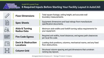
Storage Products Company's pre-layout assessment covers all of these — SKU profile, throughput, pallet dimensions, lift truck fleet, aisle requirements, ceiling clear height, fire code constraints, and building column grid — before any drawing begins.
Skill level note: Basic AutoCAD proficiency handles straightforward 2D layout work. For mezzanines, multi-level systems, or complex multi-zone operations, work with an experienced drafter or a material handling partner who delivers layout drawings as part of the project.
How to Create a Facility Layout in AutoCAD: Step-by-Step
Correct facility layout work follows a defined sequence. Jumping to equipment placement before establishing an accurate floor boundary — or skipping dimensioning before finalizing the layout — produces drawings that can't be trusted for installation.
Step 1: Set Up Your Drawing File and Scale
Configure the drawing environment before placing a single line:
- Set drawing units to architectural or decimal inches/feet to match real-world measurements
- Establish a title block with project name, date, and revision tracking
- Draw at full size (1:1) in model space — as Autodesk documents, model space is where drawing objects are created at full size, with one unit representing one inch or one foot; scaling happens in paper/layout space when preparing the drawing for printing
The most common setup error is working in default units without verifying scale. Equipment blocks and floor boundaries that appear correct on screen can print at unusable scales, rendering the drawing useless for installation reference.
Step 2: Draw or Import the Floor Plan Boundary
Establish the building envelope before placing any equipment:
- Use the LINE or PLINE command to draw the perimeter from field-verified measurements, or import an existing architectural DWG if one is available
- Confirm that column grid locations, dock doors, overhead doors, and fixed walls are all accurately represented
- Verify this layer against physical measurements before proceeding
Discrepancies caught at this stage take minutes to fix. After equipment placement, the same errors take hours. After physical installation, corrections can cost far more than either.
Step 3: Place Storage Equipment Elements
Use scaled blocks to represent each piece of equipment. Blocks should reflect real footprint dimensions sourced from manufacturer specification sheets:
- Pallet racking bays (selective, push back, drive-in, drive-thru, cantilever, flow systems)
- Shelving units (steel, wire, rivet-style, high-rise configurations)
- Mezzanines and multi-level platforms
- Dock levelers and dock equipment
- VRC material lifts and conveyors
Position each element based on how the space will actually be used:
- High-velocity SKUs positioned near dock doors to minimize travel distance
- Directional flow that avoids cross-traffic between inbound and outbound lanes
- Compatible storage types grouped together to reduce pick travel time
- Aisle widths validated against the actual forklift fleet, not generic estimates
AutoCAD shows the spatial consequences of these decisions before installation. A selective rack layout and a drive-in rack layout of the same footprint produce very different operational results. Seeing that difference on paper — before a single anchor bolt is set — is the whole point of the exercise.
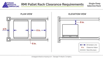
For rack placement specifically, RMI recommends 3 inches between column edge and the widest part of the load, 6 inches between adjacent loads, and 6 inches of vertical clearance to the beam above for single-deep selective configurations. These clearances should be reflected in the layout, not assumed.
Step 4: Dimension, Annotate, and Finalize
A layout without dimensions is a picture, not a planning document. Use AutoCAD's dimensioning tools to label:
- Aisle widths (all primary and secondary aisles)
- Bay depths and row lengths
- Column clearances
- Dock approach zones
- Overall floor boundary dimensions
Annotations should identify:
- Storage system types and configurations
- Load capacities where relevant (especially for racks with different beam configurations)
- Zone designations (receiving, storage, picking, packing, shipping)
- Traffic flow direction indicators
The finished drawing should be legible enough for installers to work from directly. Vague or unlabeled drawings create field interpretation errors that lead to rework — and most layout-related installation problems trace back to exactly that point: a drawing that was completed but never made usable.
Where AutoCAD Facility Layout Planning Makes the Biggest Difference
AutoCAD layouts have the highest operational impact in high-density storage environments, where the cost of a poorly planned layout compounds across thousands of daily pick-and-put-away cycles.
With U.S. industrial asking rents at $10.34 per square foot annually as of Q1 2026, wasted square footage carries a real and ongoing cost. Every row misaligned due to an inaccurate column location, or every aisle made wider than necessary, is paying rent without producing storage positions.
How AutoCAD Is Applied Differently by Situation
New warehouse buildouts benefit most from AutoCAD before construction is finalized — facility and rack dimensions can still be adjusted while they're lines on paper. Storage Products Company applies this approach to turnkey distribution center fit-outs, working from initial layout through equipment specification, installation, and commissioning.
Existing facility reconfigurations call for a different use: modeling multiple layout scenarios — selective racking versus drive-in racking, or a mezzanine addition versus expanding the footprint — and comparing outcomes before committing to a purchase. As a multi-manufacturer dealer, Storage Products Company can model configurations across Frazier, UNARCO, Cubic Designs, and other product lines within the same drawing, giving clients a clear basis for comparing options.
Verticals that benefit most:
- Distribution centers and 3PL operations with high-SKU, high-velocity picking
- E-commerce fulfillment centers using multi-level pick modules
- Automotive parts distributors with varied SKU profiles and dense shelving requirements
- Manufacturing facilities integrating raw material, WIP, and finished goods storage
- Cold storage operations where aisle constraints and equipment specs differ from ambient warehouses
Best Practices for Effective AutoCAD Facility Layouts
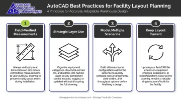
A strong AutoCAD layout depends as much on process as it does on drafting skill. These four practices separate layouts that drive real decisions from drawings that gather dust.
Start with field-verified measurements. Walls shift during construction, columns land slightly off-grid, and dock door rough openings differ from finished dimensions. A layout built on inaccurate inputs produces inaccurate results — no matter how clean the drafting.
Use layers strategically. Separate layers for the building boundary, fixed infrastructure (columns, utilities), storage equipment, traffic aisles, and safety/egress zones let you toggle visibility, share targeted views with different stakeholders, and update one element without touching the rest.
Model multiple scenarios before finalizing. AutoCAD makes it fast to duplicate and modify — test a different racking configuration, adjust an aisle width, or evaluate a mezzanine footprint before committing. Changes made on paper cost a fraction of changes made after equipment is anchored.
Keep the layout current after installation. A drawing that shows what was planned rather than what was built becomes misleading fast. Update the file whenever equipment is added, removed, or relocated.
Working with a material handling specialist who builds layouts as part of the planning process takes this further. Storage Products Company uses AutoCAD to determine the best equipment layout for warehouses, distribution centers, and manufacturing facilities before any equipment is specified or purchased — so space is optimized for both capacity and workflow before equipment is purchased.
Frequently Asked Questions
What are the four types of facility layouts?
The four types are:
- Process layout — groups similar functions (receiving, storage, picking, shipping)
- Product layout — equipment arranged in production sequence
- Fixed-position layout — product stays stationary while workers and equipment move to it
- Combination/hybrid layout — draws from multiple types
Most warehouse and distribution center layouts use a process or hybrid approach.
What is facility layout design?
Facility layout design is the process of arranging equipment, workstations, storage systems, and traffic pathways to maximize efficiency, space utilization, and worker safety. Tools like AutoCAD are used to plan these arrangements at scale before any physical implementation begins.
What is the difference between model space and layout space in AutoCAD?
Model space is where the actual facility drawing is created at full, real-world scale. Layout (paper) space is where the drawing is arranged for printing or presentation, with title blocks, notes, and scaled viewport frames. Facility layout work happens in model space.
How accurate are AutoCAD facility layout drawings?
AutoCAD can produce drawings accurate to fractions of an inch. That precision depends entirely on field-verified measurements as inputs — the software is only as accurate as the dimensions it's given.
Can an AutoCAD facility layout be updated as the warehouse grows or changes?
Yes. AutoCAD files are fully editable and can be updated at any time to reflect equipment additions, reconfigurations, or expansions. Maintaining a current layout file is a best practice for long-term facilities planning continuity.
Do I need AutoCAD skills to get a layout drawing for my warehouse?
No. Many material handling and storage system providers — including Storage Products Company — create AutoCAD layout drawings for clients as part of the project planning process. Understanding what a good layout should contain helps facility managers evaluate and use it effectively, but producing the drawing yourself isn't a prerequisite.